Introduction
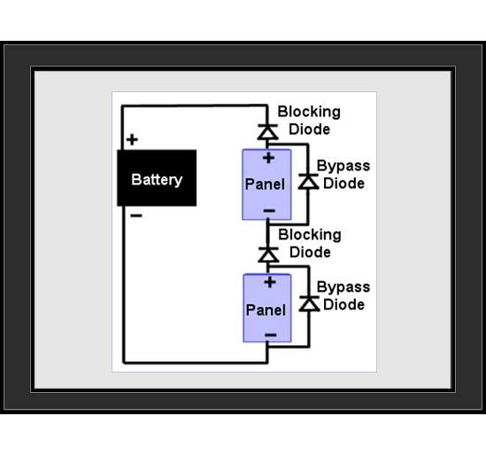
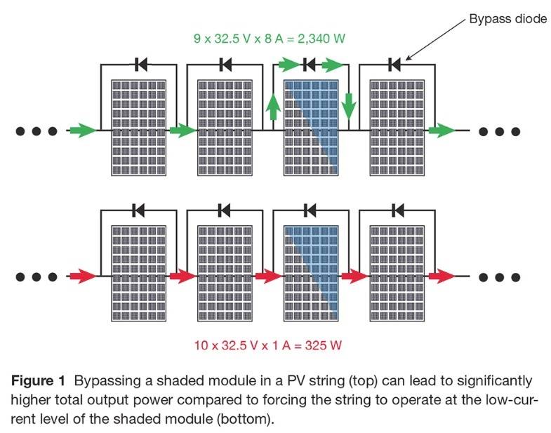
 Bypass diodes, also known as free-wheeling diodes, are wired within the PV module and provide an alternate current when a cell or panel becomes shaded or faulty. Diodes themselves are simply devices which enable current to flow in a single direction. Bypass diodes then are exactly as they sound: devices for channeling current by bypassing the solar panel itself. They typically come installed in the PV module from the module manufacturer, and are generally placed every 18-24 cells. You will typically find 2 sets in nominal 12VDC modules and 3 sets in nominal 24VDC modules. They can be installed in the module junction box or integrated into the module itself. While physically similar to blocking diodes, bypass diodes are wired in parallel with the solar cell or panel, which is in contrast to series-connected blocking diodes.
Main Functions
Safety Purposes
The bypass diode prevents “hot spots” by regulating the current from the sunlight.
Increased Power Production
When used with an MPPT charge controller, a bypass diode can increase power production under shady conditions in certain situations.
How Does the Bypass Diode Work?
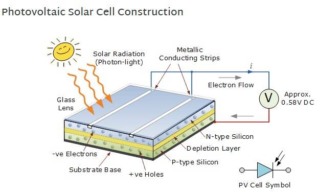
To understand bypass diodes, you first have to understand what a solar cell is and how it works. The image below depicts a basic solar cell construction. The simplest way to think of a PV cell is an LED (Light Emitting Diode) in reverse. When you run current through an LED it produces light; a solar cell works in the exact opposite way: you put light on it and it produces current. So when light is taken away from the solar cell (either at night, shading, etc.) it actually consumes power instead of producing it. The bypass diode works to regulate the current and works within the array.
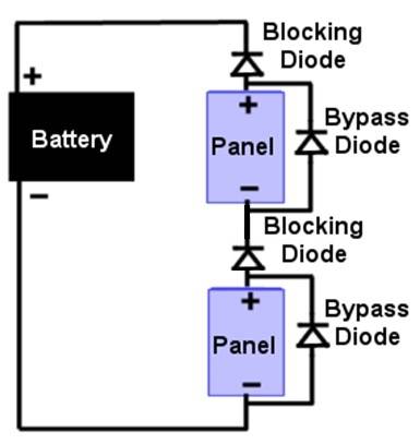
Note on the images above for the bypass diode symbol, the flat line represents the blocking of current flow, and the triangle represents the flow of current through the diode.
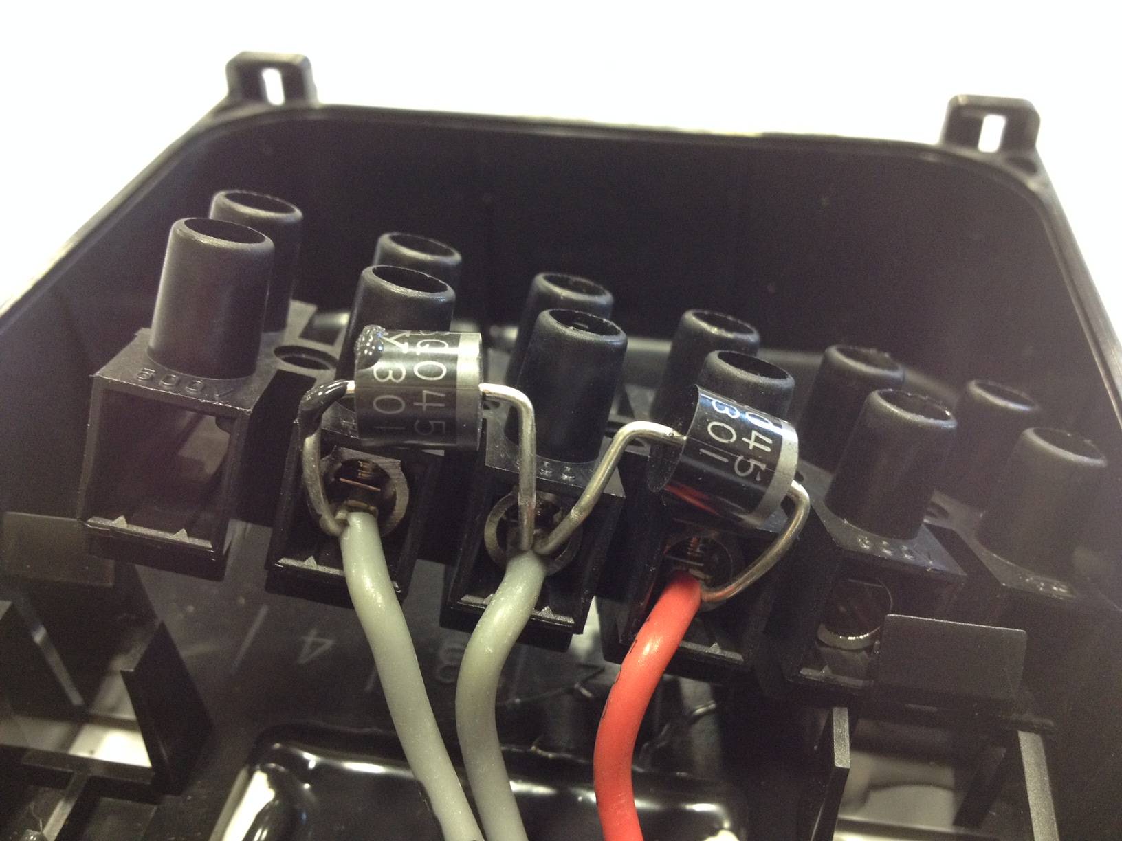
One Important thing to note on Bypass Diodes is that the flat line of the diode symbol that touches the triangle (see figure above) corresponds to the physical colored line on the actual diode itself (see picture below). This is helpful because you know which way to install the physical diode in the circuit.
Why Isn’t a Blocking Diode Sufficient?
A blocking diode can be used to prevent the current from flowing from a battery back through the array. This is typically built into the charge controller and can be done using diodes, transistors, or other method. A blocking diode is fine for a string or an array, but does not work internally. So when shading occurs, current is being produced by cells that are in the sunlight and being consumed by ones that are being shaded. This can create a “hot spot” and literally cause damage to the module. Bypass diodes allow the current from the sunlight cells to go around “bypass” the shaded cells preventing the “hot spot” from occurring.
Considerations for using bypass diodes
Reduced Total Output Voltage: increased safety requires some form of a cost and with bypass diodes it is found within the output voltage of the PV module.
As the voltage has been reduced, it is no longer high enough for battery charging using a PWM charge controller; however, if the array has been wired for a high voltage and an MPPT charge controller has been used, battery charging may continue at a reduced rate. Allowing the shaded portion of the module or array to be removed while still allowing the remaining unshaded portion to continue charging the battery.
Final Notes
When troubleshooting PV modules, the discrepancy in Voc may help to determine if the module is being shaded, if diodes have gone bad, or if the module is missing wire. For more on this, click here to refer to our PV Module Testing tech note!


